New York to Spend Billions on Climate Resiliency

Nearly eight months after Hurricane Sandy slammed the north-eastern United States, New York Mayor Michael Bloomberg is proposing a far-reaching $20 billion plan to build flood barriers and “green infrastructure” to protect low-lying areas of Manhattan from future superstorms.

Following Sandy, the mayor appointed a task force to assess the city’s vulnerability. In a report released this week based on its recommendations, the mayor cited scientists’ predictions that sea levels could rise as much as 31 inches by 2050, accompanied by severe storms and prolonged spells of extreme heat and cold.

“Hurricane Sandy made it all too clear that, no matter how far we’ve come, we still face real, immediate threats,” Bloomberg said in a speech at the Brooklyn Navy Yard, the same location where IceStone, a Sustainable Industries-profiled company, was nearly wiped out following Sandy (in this case, workers rallied to restore the factory). “Much of the work will extend far beyond the next 200 days — but we refuse to pass the responsibility for creating a plan onto the next administration. This is urgent work, and it must begin now.”

Bloomberg’s recommendations are highlighted by “green infrastructure” projects, including supporting renewable and distributed energy generation systems, planting more trees and vegetation on streets and rooftops, upgrading building codes, enhancing natural wetlands, and refurbishing drainage systems to manage runoff. The mayor also  appointed a “director of resilience” named Daniel Zarilli.

The plan is heavy on construction of stormwalls and barriers, but Bloomberg suggested these could come in the form of elevated parks and boardwalks.

The mayor’s report was endorsed by a cadre of business and environmental organizations, including the Columbia University Center on Global Energy Policy, Real Estate Board of New York, Environmental Defense Fund, Building Resiliency Task Force, The Rockefeller Foundation, NRDC, New York Smart Grid Consortium, the American Institute of Architects New York chapter, and the region’s largest energy utility, Con Edision.

“These new guidelines place New York City at the forefront of thinking on resiliency relevant for coastal communities around the world,” said Christopher Collins, executive director of Solar One. “This continues a series of strategic steps that the Bloomberg administration has taken, including investment in new, sustainable building models, to help create a new paradigm for construction that addresses both the fact of climate change, as well as the need for renewable and sustainable practices.”

How will New York pay for it all? The city can rely on $10 billion in city capital funding and federal aid, and another $5 billion in U.S. disaster relief, the mayor said. Additional federal funding and capital raised through the sale of municipal bonds would be needed to cover the remaining $4.5 billion, he added. The plan outlines a number of ways to raise the additional billions that would be required for the plan to become a reality.

Story credit: www.sustainableindustries.com

Pelamis P2 Celebrates 1 Yr of Accelerated Real-Sea Testing

The ScottishPower Renewables (SPR) owned Pelamis P2 wave energy converter has this week completed its first year of a robust testing programme at the European Marine Energy Centre (EMEC) in Orkney.

The combined P2 test programme has now accumulated 7500 grid connected operating hours, and exported 160MWh of electricity to the national grid. These are encouraging figures for this stage of the testing programme and it is anticipated that generated powers will continue to rise as the programme develops. These P2 operating hours bring the cumulative total for Pelamis technology up to over 10,000 grid connected operating hours, demonstrating both the extensive experience of the Pelamis team and the wealth of learning delivered by the P2 testing programme specifically.

Following its first installation in May 2012 alongside the E.ON owned Pelamis P2 machine at the Billia Croo test site, the machine has been undergoing a progressive work-up testing programme, being exposed to increasingly large wave conditions for longer deployment periods. An accelerated form of the work-up programme was made possible thanks to the wealth of learning accumulated since the beginning of the E.ON Pelamis P2 demonstration programme in October 2010, and the resulting confidence of both the customer and Pelamis operation teams in this testing approach.

As a result of this accelerated testing strategy, the SPR owned Pelamis P2 wave energy converter was able to generate twice the amount of electricity in half the elapsed calendar time, during its initial test parameters of small to medium seas. In deployments since then, the SPR Pelamis machine has experienced larger seas with significant wave heights of up to 5mHs, including individual waves of over 9m. Electricity generation has increased as anticipated in these larger, more energetic seas.

The proven average output capability of the device, over the annual spectrum of wave conditions at the EMEC site, is now close to 100kW. Demonstrations of further improvements are anticipated through control optimisation which could double that number as targeted for the next stage of the project.

The machines have now experienced around 90% of sea state occurrences for an average year, allowing the Pelamis team to quantify the performance and electricity output of the P2 machines and gain insight into the factors influencing this. This broad range of data from real sea testing is invaluable for the on-going development of the technology, allowing focused design and innovation for future enhancements of the Pelamis machine. These enhancements are vital to ensure that the costs of generating electricity from wave power continue to fall, in order to become cost competitive with other sources of offshore renewable energy. This is an important direction for Pelamis to take as an industry leader. Announced in February, Pelamis is working on a project commissioned and funded by the Energy Technologies Institute investigating a multitude of opportunities for performance enhancement and rapid reduction in cost of energy.

Derrik Robb, Operations Director at Pelamis Wave Power, said: “The results achieved during this testing programme are testament to how far we have progressed, working collaboratively with our customers. The wealth of knowledge and data collected to date has been instrumental in reinforcing our technical understanding of the Pelamis and its control systems and we continue to apply key learning points from one machine to the other, thus reducing time spent addressing first-of-type issues.”

Alan Mortimer, Head of Innovation at ScottishPower Renewables, said: “The past year at EMEC has been an invaluable learning experience for SPR, E.ON and Pelamis.  The collaboration has worked well and all parties have benefited from sharing of information, risks and innovation.

“The creation of the Operations Team and Health & Safety Systems has been a substantial effort this year and now provides the basis for us to explore the performance potential of the P2 machine.  The output of the device is steadily increasing as experience is gained and as the controller is fine-tuned for maximum energy extraction. We anticipate further significant improvements over the next 12 months, with the remainder of the test plan focused on optimising the power produced in the full range of sea-states in order to progress the technology towards commercially-viable status.”

Pelamis’ patented ‘plug & play’ system for the safe and rapid installation and removal of the machines in water has proved its strength and allowed for the towing and installation to be routinely conducted in wave heights of up to 2.5 metres as well as in darkness. This unique feature of the Pelamis P2 machine greatly expands the opportunities for operations and safe intervention, as it allows for flexible, round-the-clock operations, which is particularly important in the waters to the north of Scotland and over the winter months. The two Pelamis machines have been deployed in tandem during winter.

1st Grid-Connected Offshore Wind Turbine USA

University of Maine Advanced Structures and Composites Center and partners to Launch first offshore wind turbine in North America May 31.

Orono, Maine —The University of Maine’s Advanced Structures and Composites Center and its partners will hold a launch celebration Friday, May 31 at 11 a.m. for VolturnUS 1:8, the first grid connected offshore wind turbine to be deployed off the coast of North America.

The event will be hosted by Cianbro, 517 South Main Street, Brewer, Maine. Honoured guests will include members of Maine’s Congressional delegation, the Director of Maine’s Office of Energy, representatives from the U.S. Department of Energy, Cianbro CEO Peter Vigue, and business and civic leaders. The highlight of the event will be a traditional launch of the vessel by Senator Susan M. Collins.

The approximately 65 foot tall turbine prototype is 1:8th the scale of a 6 megawatt (MW), 423 foot rotor diameter design. It is the first floating turbine of its kind in the world, using advanced material systems with a unique floating hull and tower design. The program goal is to reduce the cost of offshore wind to compete with other forms of electricity generation with no subsidies.

Maine has 156 gigawatts (GW) of offshore wind capacity within 50 miles of its shores and a plan to deploy 5 GW of offshore wind by 2030. The 5 GW plan could potentially attract $20 billion of private investment to the state, creating thousands of jobs.

The VolturnUS technology is the culmination of more than five years of collaborative research and development conducted by the UMaine led DeepCwind Consortium. The DeepCwind research program is a unique public private partnership funded by the Department of Energy, the National Science Foundation Partners for Innovation, the Maine Technology Institute, the state of Maine, the University of Maine and more than 30 industry partners.

Data acquired during the 2013 deployments off Castine and Monhegan will be used to optimize the design of UMaine’s patent pending VolturnUS system.

The UMaine Composites Center has partnered with industry leaders to invest in a 12 MW, $96 million pilot farm. The deployments this summer will de-risk UMaine’s VolturnUS technology in preparation for connecting the first full scale unit to the grid in 2016.


There’s a New Twist in Wind Blades

NSE Composites used Abaqus FEA to validate a Sandia-funded sweep-twist design that captures 12 percent more energy.

The basic physics and economics of wind turbine blades are relatively simple. For one, their power output is roughly proportional to the square of blade length. This relationship pushes designers to create increasingly longer blades for harvesting additional kilowatts. Secondly, as blades get longer, weight increases—by approximately the cube of the length—leading to higher raw material costs. This correlation sends designers in search of weight-efficient geometries that are strong and rigid enough to weather the increased loading inherent in longer blades.

Navigating a maze of engineering challenges such as these can lead to interesting design directions. At the United States Department of Energy’s (DOE) Wind Energy Research Program at Sandia National Laboratories, the result has been the development of a sweep-twist adaptive rotor (STAR). This innovative curved blade was proposed in earlier theoretical research and had been garnering increasing interest for use in utility-scale applications. The new configuration is seen as a way to reduce operating loads on ever-lengthening blades. If successfully commercialized, the outcome would be larger, lighter, less-expensive, and more productive wind turbines.

In 2004, Knight and Carver (K&C) Wind Group, a San Diego-based wind blade manufacturer, was awarded a DOE contract to develop STAR. Partnering with Sandia, K&C was responsible for design, fabrication, testing, and evaluation of a sweep-twist prototype. They began by assembling a team of specialized companies and academic institutions, one of which was Seattle-based NSE Composites, who were brought on board to perform the finite element modelling (FEM) of the new design.

“NSE had done a lot of analyses over the years on composite aircraft and helicopter aero structures for companies such as Boeing,” says DM Hoyt, one of NSE’s founders. “Plus, we were already troubleshooting another blade problem for K&C and wanted to diversify our customer base to include more renewable energy, so the fit was a good one.”

Hoyt and his partners at NSE have been using Abaqus from SIMULIA, the Dassault Systèmes application for realistic simulation, as their finite element analysis (FEA) tool for years. As their projects moved toward larger and more complex models, the software’s ongoing developments in simulating composites, crack generation, and fracture kept pace.

“Simulation has been a great asset for both our aerospace and wind energy work,” says Hoyt. “It enables us to explore new ideas and look at the performance of multiple designs and materials while minimizing expensive testing.”

Sweep-twist blade basics

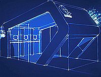
Rather than a traditional linear profile, a sweep-twist blade has a distinctive gently curving tip (or “sweep”) with curvature towards the trailing edge (see Figure 1). Theoretically, this planform shape allows the blade to respond to turbulent wind gusts through a process of controlled twisting and bending: As the blade twists, it sheds loads that would normally be translated as material stresses to the root (or base) of the structure. In nature, a similar sweep can be seen in the wing shape of birds that migrate long distances and the characteristic profile of whale tails and dorsal fins.

The engineering upside of twist-coupling is the ability to create longer wind blades while avoiding the higher loads that typically accompany increased length. Reducing loading—not only on the blade root but also on the turbine itself—enables a lighter blade design with lower raw material costs and helps lessen fatigue stresses on the rotating machinery. In early calculations, the STAR design promised a decrease in fatigue loads of 20 percent using a tip twist of three degrees. But as the design progressed, longer blades that capture more energy with no increase in load were pursued.

Beyond the potential advantages of altering the traditional length-weight-cost relationship, twist coupling is seen as a financially attractive solution for tapping low-wind-speed sites (defined as having an average velocity of 5.8 meters per second at a 10-meter height). These sites—in contrast to the high-wind-speed locations that have been the focus of wind-mining to date—are abundant in the U.S.’s mid-section and closer to major power-load centres. If the cost benefit proves favourable, development of low-wind locations could increase potential domestic wind farm area by a factor of twenty.

Understanding turbine behaviour — without the wind

“Over the years wind blades have become more and more high tech. The industry is pushing the limits of design and materials,” says Hoyt. “As that happens, engineers need to tighten up the loose legacy tolerances and manufacturing controls that originated in boat-building technology and adopt the more rigorous analyses that we have always done for complex aerospace structures.”

Of particular use in wind blade analyses with FEA, notes Hoyt, is Abaqus’ ability to handle composite properties and control material orientation. It can calculate blade-tip deflection (to avoid “tower strike”) and accurately predict both torsional response (including twist angle, which is key to load-shedding) and shear-compression buckling stability (associated with sweep-twist) of composite sandwich structures. An additional capability key to wind blade analysis is the extraction of accurate equivalent beam properties directly from a solid 3D FEM. These bending and twisting definitions are used in wind-blade-specific dynamics codes to predict the overall performance of the turbine.

“During the preliminary design phase, the type and amount of input data is often limited,” says Hoyt. “In the wind projects we’ve been involved with to date, there hasn’t been a high-fidelity CAD model available to use as a basis for the FEM.” So at the start of the STAR analysis, the NSE team only had the blade’s basic geometric parameters—the planform shape, the air foils, and the chord lengths—to work with. The desire for high-fidelity FEA at a design stage when only the basic parameters of the blade have been defined led to the development of NSE’s bladeMesher software, which is able to create a solid 3D mesh of the blade from the partial data.

“Our software splines the geometry defined at several locations on the outer mould layer (OML) of the blade and combines it with the composite material thicknesses specified at each location to generate a mesh with the true thickness details,” says Hoyt. “This solid mesh and material definition is then imported into Abaqus where we perform a detailed finite element analysis. We have found that a solid FEM has many advantages over shell element FEMs, which have traditionally been used for blade analysis. These benefits include a more accurate prediction of twisting behaviour and the ability to analyse stresses in the adhesive joints between structural elements.”

As the design of the blade progressed, the team explored new air foils and made adjustments to the sweep geometry to hone in on the optimal amount of twisting. The bladeMesher software enabled rapid updates to the solid FEM based on the new geometry, allowing the team to quickly assess the effect of each change. Abaqus’ task was to confirm the earlier section analysis predictions, which were performed using constant-section-equivalents to estimate the effective beam properties of the blade.

To determine whether the sweep-twist geometry would shed loads as predicted, two wind scenarios were applied to the model: an operating load and an extreme-wind conditions case (50-year gusts at 156 miles per hour). The analysis was used to predict the blade deflection and twist, perform detailed stress calculations, and investigate potential shear buckling due to the increased twist inherent in the design.

US Army Shelter Constructed of Composite Material

Based on the use of 20-foot ISO shelters in some of their systems, PD TMDE was asked to serve as the project sponsor and requirements provider for an Army Research Laboratory project to research and develop a new shelter for the Army constructed of composite material.   The program, called the C-4 shelter, resulted in a lightweight, corrosion resistant shelter that is lightweight and promotes energy efficiency. A lighter-weight shelter with improved insulation and other energy efficient characteristics greatly reduces transportation and operating expenses.   ARL with the assistance of Natick Shelters Technology, Engineering and Fabrications Directorate ensured the shelters met current and future requirements for government use. The C-4 shelter is composed mostly of carbon, epoxy and fiberglass material with very little dependence upon metal except for the exterior ISO corners. Two types of shelters were built − one with an 80db Electromagnetic Interference/High Altitude Electromagnetic Pulse shielding and the other unshielded.

The shielding proved to be superior to the shielding of previously acquired shelters providing protection of valuable electronics in the event of an electromagnetic attack. Even though 40 percent lighter than aluminium and steel shelters presently in use, the composite shelters have a greater strength per unit density than aluminium and steel giving it a superior strength to weight ratio. The C-4 shelters have a tare weight of 5,760 pounds with a maximum payload of 14,240 pounds. The C-4 shelters have passed the International Convention for Safe Containers certification. Shelter temperature is controlled by standard environmental control units and use LED lighting instead of florescent or incandescent which can be dimmed or changed to a blackout colour.

The C-4 shelter built has a thermal resistance value of R-8 which far exceeds the ASTM standard of R-2.86. Shelter service life is estimated to be 30 years with lower maintenance costs; much of the shelter is field repairable. The shelter includes replaceable/repairable ISO corners and forklift pockets using hardware attachable components. This is a feature not found on any other ISO containers which is a major savings in cost and time in a depot.

UK Innovator Recycling Glass & Carbon Fibre Waste

SIS would like to congratulate FORMAX.

FORMAX has launched a new recycling initiative at its UK production facility. Thanks to the creation of a dedicated Recycling Division and the installation of two bespoke machines, FORMAX say it is now able to reprocess the majority of its glass and carbon fibre waste.

FORMAX state the recycled materials are suitable for a variety of non-structural and structural applications across a range of industries, and a number of its customers are already manufacturing components using products from the division.

“Last year we generated over 600 tonnes of glass waste so recycling is clearly very high on our agenda, both from a position of environmental responsibility, but also from a commercial standpoint. The market for recycled materials is a growing sector with a number of significant opportunities and the creation of our new Recycling Division allows us to devote considerable time and resource into optimizing products for these processes” comments Oliver Wessely, Managing Director of FORMAX.

Multipurpose Modules for Sustainable Buildings

Edra Equipamentos has launched a multipurpose module for commercial construction applications.


The company say that the module, called “e.modular” can be used for instance, as a “pop-up” shop, for the showroom of real estate developers, cafeterias, help desk at events and even self-service banking kiosks.


Edra Equipamentos state the e.modular is a 3.2m wide, 6m long steel structure with composite coated walls and ceiling. The resin used for moulding the composite plates is partially derived from renewable and recyclable sources, such as oil plants and PET bottles. The floor is made of plastic wood composite and comprises of more than 90% discarded packaging waste.


The company added that during the day, the natural lighting of the e.modular is ensured by a system called Solatube, which captures and diffuses the light in the environment. To reduce the energy consumption of air conditioning, Edra Equipamentos applied special 3M film on all glass surfaces, which prevents the passage of more than 80% of infrared rays.


In terms of accessibility, the e.modular includes a wheelchair ramp, automatic doors and adapted bathrooms. Signed by São Paulo architect, Tatiane Rocha, the project makes use of curved lines and large transparent areas to increase the feeling of space.


“The design is both externally and internally modular. This means that users are totally free to define how they want to use the space. Not to mention that it is possible to overlap the modules, creating two or more floors,” says Jorge Braescher, president of Edra Equipamentos.

Composite Wing Components for Airbus A350 XWB

GE Aviation, Hamble has achieved a major program milestone with the delivery of its initial production wing fixed trailing edge components for the first A350 XWB to fly – ‘MSN001’. The first A350 XWB-MSN001 is now structurally complete and is currently undergoing ground testing in Toulouse.

The A350 XWB wing fixed trailing edge package is the largest production contract awarded in GE Aviation Hamble’s 75-year history, comprising more than 3,000 components that include structural composite panels and complex machined assemblies. The A350 XWB has a total wingspan of more than 64 meters.

“This delivery start up results from major achievements at GE Aviation in design and manufacturing – bringing together new tool sets, materials and technologies, while also involving concurrent engineering with global suppliers to obtain material and long-lead items in unprecedented timescales,” said Steve Walters, executive product leader for GE Aviation’s aerostructures and nacelle activities. “We have proved our capabilities and have created a secure foundation to build on for the future.”

GE Aviation will provide the wing fixed trailing edge for all three A350 XWB family members: the A350-800, -900 and -1000.

The company began its work on the wing components in October 2008, progressing from a very basic conceptual design while enhancing its management to address the project’s magnitude. In addition to increasing the scope of GE Aviation’s own technical capabilities, the company involved a global design team that included GE Aviation resources in Poland and India.

“During the program, GE Aviation, as risk-sharing partner, developed a close working relationship with Airbus, as the aircraft manufacturer providing advice, assistance and support that enabled us to meet this major delivery milestone,” Walters added.

In addition to major investments already implemented at the Hamble-le-Rice factory in Southampton, Hampshire for A350 XWB production, the site will see further enhancements with the creation of a new composites facility dedicated to this Airbus program.