News

WPC to clad the new Australian Embassy in Jakarta

Back in early 2009, our Offshore Product Manager, Mr. Nick Wotton began collaborating with global architecture firm Denton Corker Marshall on a timber alternative recycled wood plastic composite (WPC) profile to clad the new Australian Embassy in Jakarta. After five years through design to construct, the new embassy is nearing completion and the cladding product developed by Nick is soon to be installed on the project providing the Department of Foreign Affairs & Trade (DFAT) a sustainable and maintenance free product made to suit the equatorial climate of Indonesia.

A Landmark Composite Pedestrian Bridge

A new pedestrian bridge over Rhyl Harbour in North Wales consists of two 30 m long composite lifting decks. This is the story of its design and installation.


FRP composite bridges – a brief history


Bridges have traditionally been manufactured mainly from steel or concrete and alternative materials are rarely considered. However, the last 15 to 20 years has seen an increasing use of fibre reinforced polymer (FRP) composites in bridge construction.


Initial applications in Europe were limited to pedestrian and cycle bridges and there are now hundreds in service. In the USA composite decks and occasionally beams are increasingly used for both pedestrian and road bridge construction, but 100% composite structures are still rare.


Advantages of composite bridges Reduced mass (typically 2 tonnes for a 12 m pedestrian bridge):

  • smaller cranes required for installation;
  • smaller foundations require less subterranean excavation and disruption;
  • easier to manufacture offsite in fewer parts;
  • quicker to install, minimising possession times.


Increased durability:


  • 100 year design life is now common;
  •  resists atmospheric corrosion;
  •  resistant to most chemicals, fuels, de-icing salts, etc.;
  •  paint systems don’t degrade due to corrosion of the substrate.
  •  greater freedom of form;


More sustainable:

  • lower embodied energy;
  • less fuel used for transportation.

Electrically insulating:

  • desirable for some applications.

Composite bridges offer a number of significant advantages over those manufactured from metal or concrete (see box).

In the UK, 100% FRP composite bridges are still few in number and they have yet to appear as mainstream structures. The majority of applications involve the use of composite materials for decks and balustrade systems manufactured using the pultrusion process alongside steel or concrete primary structural elements, or for strengthening of existing steel or concrete structures.

This slow take-up of the technology is the result of a number of reasons:

  • lack of relevant design codes;
  • lack of structural engineers experienced using FRP materials;
  • lack of general knowledge on the properties of FRP materials;
  • lack of reliable materials properties data.


Many universities have been slow to add a significant composites element to their materials and engineering modules and this has inhibited the growth of application of composite materials in the construction industry. However, with the development and introduction of relevant design codes such as the new Eurocodes, and work undertaken by NGCC (Network Group for Composites in Construction), Composites UK and other specialist trade associations, the number of applications has begun to grow.


In the UK, both the Highways Agency and Network Rail have experimented with FRP bridges. The Asset West Mill road bridge completed in 2002 was the first 100% FRP UK road bridge, and Network Rail have now completed three all-composite pedestrian bridges, each using a different method of construction.


The first bridge was installed in St Austell and constructed using a series of pultrusions and moulded fairings. The Bradkirk Bridge, located near Blackpool, was manufactured by composites company AM Structures in 2009 and is the only moulded bridge of the three. The third bridge is installed at Dawlish station and is constructed using pultrusions, sandwich panels and moulded stairways.


The moulding process offers a number of advantages:

  • it allows far greater freedom of form for the architect;
  • it results in a more efficient structure and use of materials, and thus lower weight;
  • it results in a structure with fewer, or no joins leading to greater reliability and less installation cost.


However, a moulded bridge can require a greater level of engineering skill due to a more complex geometry. The Rhyl Harbour Lifting Bridge is one such bridge.


Innovation in design – a landmark structure

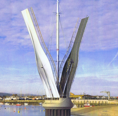
In response to a tender call from Denbighshire County Council for a new lifting bridge over Rhyl Harbour in North Wales, engineering and design consultancy Ramboll and civil engineering and building company Dawnus developed a design proposal consisting of two mirroring 30 m long decks which are hinged on a central caisson and lifted by cables running up to a central mast.


Almost 50 m tall, the mast is stayed by rigging similar to a sailboat’s and makes the bridge and the harbour visible from miles around. The pulley mechanism and lifting cables are located within the central mast. To balance the lift the mirroring decks are lifted simultaneously.


The mast is structural up to the lower spreaders and purely architectural above. It is fabricated from duplex stainless steel.


The new bridge serves as an additional crossing for pedestrians and cyclists, spanning the River Clwyd from Rhyl’s West Parade to a newly created public area on the Kinmel Bay side of the river. The elegantly designed opening lightweight bridge has already become an iconic landmark attracting many visitors to the area.


Lightweight and sculptured deck geometry
Denbighshire County Council was interested in minimising the use of energy for each lifting operation.

To give access to moorings upstream of the bridge, the new pedestrian and cycle crossing is likely to be opened several times a day and Denbighshire County Council was interested in minimising the use of energy for each lifting operation. The use of moulded structural FRP composite materials for the bridge decks became an integral part of the design concept to save as much weight as possible to reduce lifting time and reduce power consumption. It also allowed a more sculptured deck shape, which provides a striking, iconic sight when the bridge is opened.


Ramboll approached AM Structures in early 2009 to review the concept of the bridge span construction and to provide feedback on the manufacturing process and weight estimate. AM Structures worked with structural engineering and composite materials specialist Gurit to review the structure of the bridge, and an initial study confirmed that the bridge concept was feasible with some minor changes to the underside geometry, and that the FRP decks would result in considerable weight savings compared with a steel structure.


The updated design proved to be successful and AM Structures was awarded a design and build contract by Dawnus for the fabrication of the two bridge spans.


Thorough analysis of dynamic behaviour
Having worked with Gurit previously on the Bradkirk Bridge and many other high profile structures, AM Structures contracted them to carry out the detailed structural engineering of the bridge decks.


These presented some interesting challenges. The decks are very slender, partially for aesthetic reasons, but also to ensure that the inshore lifeboat would have sufficient headroom to pass under the lowered bridge at all tide levels. Due to the complex geometry, lightweight and slender design of the decks, detailed consideration of the dynamic behaviour of the bridge under pedestrian loading was required.


The bridge was designed with predominantly glass reinforcements with longitudinal stiffness enhanced by local planks of carbon fibre. The internal structure comprised a series of transverse bulkheads and longitudinal beams laid into a sculpted structural shell. The decks were manufactured in typical sandwich form and topped off with a proprietary non-slip wear layer. Balustrade mounting brackets were invisibly bolted to the internal transverse bulkheads.


Gurit made extensive use of finite element analysis (FEA) to carry out transient dynamic analysis of the bridge using load models from Eurocodes. A number of load conditions were analysed, corresponding to groups of pedestrians walking and running over the bridge, in addition to a crowd loading case. This analysis led to optimisation of the laminates for both longitudinal and torsional stiffness of the bridge decks to meet the required comfort criteria.


Quality control of manufacture
Using the client’s geometry 3D file direct mould tooling was manufactured from CNC machined expanded polystyrene foam which was skinned with an epoxy laminate and then faired and finished to achieve the high quality finish that was required.


AM Structures built the bridge using Gurit’s Corecell™ M-Foam (a structural foam core material based on a SAN polymer base), Ampreg 21 epoxy resin and a mixture of glass and carbon reinforcements. QE1200 woven glass multiaxial was used for most of the structure providing a low reinforcements cost per kg. The fabric was wet out using a machine in order to reduce labour costs and better control the fibre volume fraction of the finished laminates. Woven glass biaxial (typically XE900) was used for over-taping and reinforcing joints within the bridge structure. Carbon planks were incorporated into the deck and lower bridge structure to provide longitudinal strength and stiffness and these were laid up from UC800 unidirectional carbon.


The client free-issued various steel fabrications used for hinges and lifting points as well as stainless steel plates used for the mounting of the balustrades. AM Structures incorporated these into pre-prepared apertures in the structure. An alignment jig ensured that the bridge lifting hinge bracketry was perfectly positioned.


AM Structures contracted Wizz Composites to advise on quality assurance requirements, develop the Quality Plan and advise on quality control activities, testing and documentation. Developing a comprehensive Quality Plan at the outset of the project ensured quality control of the finished structure.


Assuring the quality of manufacture of a substantial structure such as a bridge is always a concern of clients and end users who are often unfamiliar with FRP composite materials and their manufacturing processes. For a steel structure, a typical QC regime covers materials properties and certificates, welder qualifications, weld consumables certificates, weld procedure qualifications, non destructive testing of welds and so on, and these procedures are well understood and documented.
For a composite structure, materials properties are developed during the manufacturing process as the resin cures within the laminate matrix making the process of confirming the properties of the cured system more complex than simply obtaining a mill certificate from the provider. However, in many other respects the QA process for a composite structure can mirror one for a steel component, helping build client confidence and assuring that the structure behaves in the manner predicted by the structural engineer.


The QA regime for the Rhyl Harbour Bridge was comprehensive and included materials certificates and traceability, batch testing of component parts of the structure including main skins, bulkheads and deck panels. Tests carried out included laminate testing to verify laminate mechanical properties and DMA testing to verify state of cure and accuracy of resin mix ratios.


Within the bridge decks AM Structures provided cut-outs and installed trunking for a series of colour changing LED lights which ensure that the bridge presents a truly spectacular sight when lifted during darkness.


Transport and installation
The build of the decks was already a spectacular sight in AM Structure’s Isle of Wight factory and the shipment on the car ferry to the mainland, the onward transportation to Wales and the lifting of the decks into place, all attracted crowds.


More AM Structures projects Several AM Structures projects can be seen around the UK, including Ron Arad’s Big Blue at Canary Wharf, the three Light Wands (masts) at the Birmingham Bullring, the 33 m carbon composite bridge roof structure (which resembles a surfboard) at Langdon Park DLR Station and the Bradkirk Bridge supplied for Network Rail.


AM Structures also supplied the two 26 m feature lighting masts for the Poole Twin Sails Bridge and a number of 35 m Dune Grass flexible spars installed on Blackpool’s Golden Mile.

Each bridge span, which resembled the shape of a tuning fork in plan, was split lengthwise to reduce its width for road and ferry transportation. The finished walkway width is 4 m at the widest point, with each small leg being 3 m wide. Each half was preassembled with its mating part in the factory to ensure a perfect fit. Once at site the two halves of each span were bonded together using Gurit’s Spabond 340LV structural adhesive and located with two rows of bolts. Access to the inside of the bridge was achieved via hatches located in the deck surface.


The total weight of one complete span including hinge and balustrade supporting steelwork was 10.6 tonnes. Steelwork added a further 3.2 tonnes to each span. This represented a very considerable weight saving over the concrete or steel alternatives.


By the middle of July 2012, hundreds of people had flocked to Rhyl with their cameras to catch the moments when the 30 m long decks were lifted into place.


The new crossing needed a catchy name and so a naming competition was opened up to pupils at local primary schools. An independent panel considered over 30 names and finally selected “Pont y Ddraig” (The Dragon Bridge), as one student had suggested. The bridge was opened to the public on 22 October, when all pupils who had participated in the naming competition led the first walk across.


Story Credit: Reinforced Plastics Magazine

NASA satellite on mission to Mars boasts composite components

CAPE CANAVERAL, FLA. — Plastics are headed back to Mars in the composite structure of the latest NASA satellite to study the planet.


TenCate Advanced Composites NV supplied the carbon fibre composite that is part of the MAVEN — which stands for Mars Atmosphere and Volatile Evolution — project. MAVEN headed into space during a Nov. 18 launch from Cape Canaveral.


MAVEN is specifically designed to collect data from Mars’ upper atmosphere, unlike other high profile projects such as the Rover. NASA officials noted in a Nov. 14 news release on the project that Mars once had surface water, but the atmosphere thinned and it lost that water. Scientists speculate that the sun may have played a role in allowing vital gases to escape from the atmosphere, but have not been able to confirm that.


“Mars is a complicated system, just as complicated as earth in its own way,” said Bruce Jakosky, the mission’s principal investigator. “You can’t hope, with a single spacecraft, to study all aspects and learn everything there is to know about it. With MAVEN, we’re exploring the single biggest unexplored piece of Mars so far.”


MAVEN is a 7.5-feet by 7.5-feet by 6.5-feet cube built out of composite panels made with an aluminium honeycomb core sandwiched between composite face sheets. The entire structure weighs 275 pounds, but was designed to support the entire spacecraft mass during launch.


It is expected to reach Mars’ upper atmosphere and begin its mission in September.

SIS Builds Relationship with Global FRP Leader

Today our Director – Products & Structures Mr Nick Wotton has welcomed to Australia Mr Tom Carlson, Manager – Offshore Markets at Strongwell Corporation Inc (USA). Today marks the beginning of a new global partnership between SIS and Strongwell Corporation.


Strongwell is the world’s largest pultrusion company and the recognized leader in the pultrusion industry. Strongwell has pultruded fiber reinforced polymer (FRP) composite structural products since 1956 and today offers unequaled capacity, versatility and flexibility to meet the needs of its customers and allied partners.


Strongwell has been manufacturing high quality fiber reinforced polymer (FRP) products using “the continuous automatic process” (today known as “pultrusion”). Today, with three manufacturing locations, 65+ pultrusion machines and more than 645,000 square feet of manufacturing space.

Boeing & Oracle to Recycle Largest ever Carbon Fibre Structure

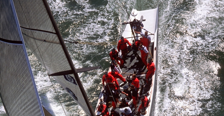
Boeing and Oracle Team USA, winners of the 34th America’s Cup, are collaborating to recycle over 3 tonnes of carbon fibre from the USA-71, a yacht built for the America’s Cup campaign in 2003.


The hull and mast of the racing yacht will be processed and repurposed, a first-of-its-kind effort for what will likely be the largest carbon structure ever recycled.


Boeing and the Oracle team, working with research partners, will utilise a technique developed to recycle composite materials from Boeing’s 787 Dreamliner, which is 50 percent composite by weight and 20 percent more fuel-efficient than similarly sized aircraft. Composite materials allow a lighter, simpler structure, which increases efficiency, and do not fatigue or corrode. In yachts, composite construction also provides the ability to develop a lighter vessel that is stronger and stiffer at the same time.


Chris Sitzenstock, ORACLE TEAM USA logistics said;

‘The introduction of composites in yacht construction was a major step in our sport. The materials and processes have continued to evolve, allowing us to build the high-tech, high-speed AC72 catamarans raced in this year’s America’s Cup, now we have the ability to work with Boeing to take the next steps in composite recycling, and to help reduce our environmental footprint. We will also look to recycle carbon components remaining from the build of our yachts.’


Boeing and Oracle Team USA will work with the University of Nottingham in the United Kingdom and MIT-RCF, a South Carolina company specialising in repurposing carbon fibre components. In 2006 Boeing began collaborating with the University of Nottingham on carbon fibre recycling and they continue to work on recycling processes and technology to process the recycled fibre into new applications.


USA-71’s hull will be cut into 4-foot sections and the mast will be chopped into manageable pieces before it is processed; about 75 percent of the recycled composites will come from the hull and the remaining 25 percent from the mast.


Boeing and Oracle Team USA expect to gather data about the mechanical properties, costs and time flows to recycle sailing-grade composite materials in comparison to aerospace-grade and automobile-grade composites. Although the companies have not determined the post-recycling use of the yacht’s carbon fibre, potential end uses include consumer and industrial products.

76m Carbon Fibre Mast Leaves Factory

Future Fibres completes work on 76 metre mast for Perini Navi’s latest superyacht.


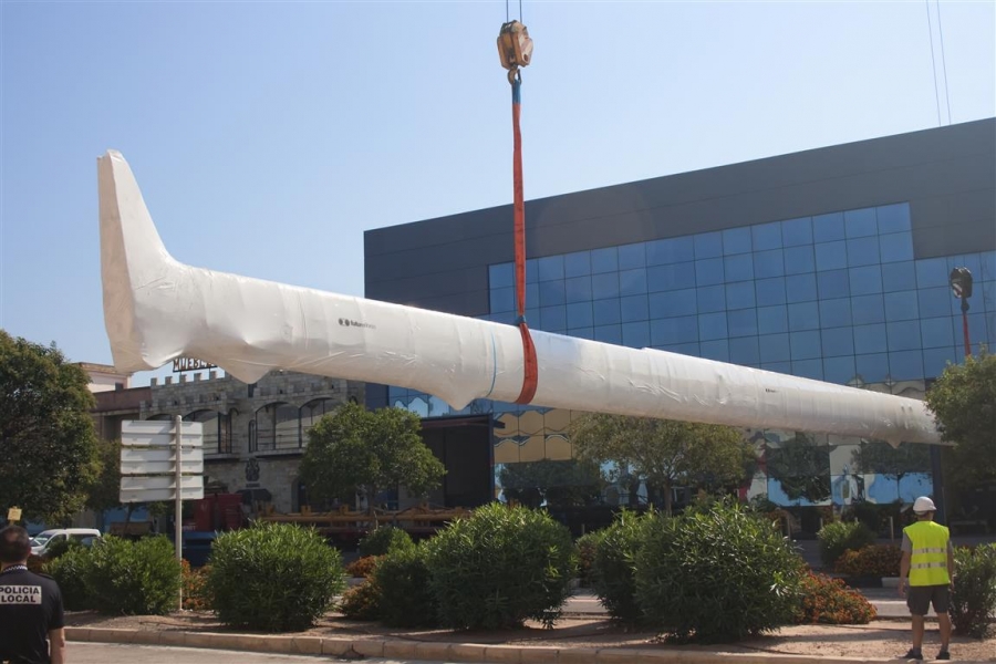
Following almost 18 months in design, development and construction, Future Fibres this week shipped its latest carbon fibre mast to Perini Navi’s La Spezia yard in Italy. Destined for the 60 metre sloop C.2218, as she is currently known, the 75.8 metre mast was built and shipped in two sections and will be joined over the next six weeks in the Perini yard. The accompanying Future Fibres furling boom and bespoke composite rigging package will be shipped later this month, with dressing and stepping of the rig due to take place in November.


The brief for project C.2218 focused on achieving the highest levels of performance and meant Future Fibres was able to utilise its extensive Grand Prix experience, incorporating many of the developments identified through its racing clients. However, with Future Fibres’ trade mark, milled aluminium, tooling they have managed to produce a tube with a perfect exterior surface and a flawless ‘Clearcote’, gloss carbon finish. The result not only looks impressive but with zero filler – which can add up to 3 per cent to the weight of a mast – further reduces unnecessary weight to deliver a mast with both performance and style.


Utilising Future Fibres’ 40 metre dedicated clean-room/oven meant the 23.4 metre furling boom could be manufactured using pre-preg carbon, rather than standard wet-laminate, improving structural performance and again, reducing weight. The boom has been through a detailed design and development process with special attention on the complex systems required for sail furling and handling. The result is a new mandrel furling and locking system which has gone through extensive testing and prototyping.


Tim Meldrum, Chief Designer for the project commented: “Bringing the innovations we’ve developed for the race market to a superyacht of this size certainly represented a challenge. We invested a tremendous amount of time into the design and management of the project to ensure we understood every variable down to the smallest detail and we are very pleased with the outcome. Once launched, C.2218 will have a hugely powerful Doyle Sails sail plan and a complete Future Fibres rigging package. The lateral rigging is solid carbon with a mix of carbon, PBO and Kevlar for the fore and aft cables. The enormous code zero is using the top-down furling technique for improved system safety and the cable required is the longest and most powerful furling cable we have ever produced. We even had to extend our winding bed through the end wall of the factory to build it! That alone is exciting but it’s just a tiny part of what should be an incredible boat and a real challenger on the superyacht race circuit for years to come.”


Quickstep’s RST Technology Passes Test

Quickstep is an Australian Company and approved supplier for the international F‐35 Lightning II Joint Strike Fighter (JSF) program ‐ the largest military aerospace program in the world, valued at in excess of US$300 billion worldwide. To date more than 68 JSF aircraft have been delivered to the US Department of Defence, and this number is now expected to grow rapidly. The company has also been selected by Lockheed Martin as the sole supplier of composite wing flaps for the C‐130J “Hercules” military transport aircraft. Quickstep is currently partnering with some of the world’s largest aerospace/defence organisations, including the US Department of Defense, Lockheed Martin, Northrop Grumman, Airbus and EADS.


Quickstep is also developing patented manufacturing technologies to produce high‐volume A‐grade finished composite components for automotives and specialist thick parts such as spars and wing skins for large defence and commercial aircraft. The company is currently working with the US Department of Defence to qualify its patented Quickstep Process and Resin Spray Technology (RST) for JSF, and is also conducting a major research and development program with car maker Audi aimed at delivering high‐quality finish, low cost, fast processing of carbon fibre composite, together with specialised resins, particularly adapted to the automotive industry.


Quickstep’s RST technology passes test from luxury car maker:

  • Quickstep’s resin spray transfer (RST) technology meets ‘spectacular finish’ test;
  • Quickstep RST passes European car marque’s rigorous environmental tests;
  • Potential significant commercial market.

Quickstep Holdings Limited – manufacturer of high‐grade carbon fibre composite components, today announced that its resin spray transfer (RST) technology has passed one of the industry’s toughest environmental test regimes for carbon‐fibre composite body panels. Results of these tests, by a prestige European car maker, have confirmed the RST technology’s ability to meet rigorous painted panel benchmarks and enable outstanding finishes. This pre‐qualifies RST technology for consideration in the marque’s commercial supply tenders.


Carbon‐fibre composite technology is increasingly a feature of highly distinctive, contemporary luxury vehicles. However, achieving top‐quality paint finish and keeping that quality over time is much harder using carbon‐fibre than metal.


Passing the stringent painting and surface ageing tests of a European luxury car maker is a feat that very few other composite technologies have achieved and, importantly, Quickstep’s RST process can be delivered at considerably lower expense.


Quickstep’s Managing Director Philippe Odouard said that this was another positive step toward securing commercial entry into the automotive market.


“Luxury cars demand absolutely flawless paint and body work, and these tests by a luxury car maker demonstrate that Quickstep’s resin spray transfer technology can support such results. During tests the car panels, manufactured using Quickstep’s RST, were subjected to hot and cold ageing cycles for weeks and subjected to high humidity and high temperature environments. We are delighted that the RST technology has passed what is considered to be one of the automotive industry’s most exacting ‘quality of finish’ tests.


“We believe that our RST technology can revolutionise car manufacturing across the globe, as it meets the industry’s three key manufacturing objectives ‐ producing strong yet light vehicle parts with fast processing, at low cost and with a high quality finish.


“The technology is drawing increasing interest, and we are progressing negotiations and providing quotes for several leading European car makers.”


The RST technology utilises an innovative ‘robotised’ process that fully automates production of lightweight carbon fibre composite car panels so they can be made in minutes and at very low cost compared to other, more capital‐intensive methods.


Quickstep is working with a number of car makers, particularly in Europe, to qualify and develop the RST process for each marque’s specific requirements. One example is Audi AG which, teamed with Quickstep in a consortium funded by the German government, is developing cost‐effective solutions for high‐volume automotive composite parts production using the RST technology, and component trials are now underway.

GE Aviation Begin Testing New Composite Fan Blades

GE Aviation has begun testing on its new composite fan blades for the GE9X, the next-generation GE90 engine that will power Boeing’s 777X aircraft. This validation test is the first of several testing programs GE has planned this year for the GE9X fan module.


The first round of fan blade tests occurred in June at the ITP Engine testing facility in the UK and focused on validating the new composite material for the fan blades. GE plans a second round of tests at ITP later this summer to further validate the new fan blade composite material and a new metal material for the blades leading edge.


The GE9X fan blade will feature a new high-strength carbon fibre material with a steel alloy leading edge, the new material, along with a higher fan tip speed, will improve the efficiency of the low-pressure turbine (LPT) and deliver more than 1.5 percent fuel efficiency improvement compared to the GE90-115B engine.


The GE9X fan module incorporates several unique features. The GE9X front fan will be the largest of any GE engine at 132 inches in diameter and include a durable, lightweight composite fan case similar to the fan case on the GEnx. Compared to a metal fan case, the composite fan case will lower the weight by 350 lbs. per engine.


The fan blades in the GE9X engine will be fourth-generation composite fan blades. GE Aviation developed the first composite fan blade for its GE90-94B engines back in 1995. Composite fan blades are also featured in the GE90-115B and GEnx engines. GE has accumulated 36 million flight-hours with composite blades and anticipates accumulating more than 100 million flight-hours when the GE9X enters service later this decade.


The GE9X engine will have 16 fan blades, which is fewer blades than the GEnx and the GE90-115B engines. This fan blade reduction is possible as a result of advancements in three-dimensional (3D) swept design that enables engineers to create a more swept design and large fan chord. The new high-strength carbon fibre material allows the blades to be thinner than blades made from current carbon fibre material, with the same strength and durability. These improvements will drive fuel efficiency improvements and hundreds of pounds of weight reduction from fan blades and the structure needed to support them.


The lower blade count and new carbon fibre composite material will enable the company to increase the fan tip speed. The increased tip speed will improve the efficiency of the LPT, enabling a reduction in the LPT blade count and contributing to the engine’s fuel burn improvement.


The GE9X engine for Boeing’s 777X aircraft will be in the 100,000 pounds thrust class with a 10 percent improvement in fuel burn over today’s GE90-115B. Key features include: a 132″ fan diameter; composite fan case and fourth-generation composite fan blades; next-generation 27:1 pressure ratio high-pressure compressor; a third-generation TAPS (twin annular pre-swirl) combustor for greater efficiency and low emissions; and ceramic matrix composite (CMC) material in the combustor and turbine.


GE Aviation has been conducting tests on new materials and technologies for the engine during the last few years, along with fan blade tests at the ITP Engine testing facility in the United Kingdom, the company will test a high-pressure compressor rig at GE’s Oil & Gas facility in Massa, Italy, this month. The first engine will test in 2016, with flight-testing on GE’s flying testbed anticipated in 2017.


This Autumn, GE plans to run Universal Propulsion Simulator (UPS) fan performance tests on a fan rig at a Boeing facility in Seattle, Washington. Work is already under way on the fan rig and facility for these tests.

US Army adopts Stronger, Lighter Composite Materials

In the future, Army aircraft may be made of all composite materials, and the Prototype Integration Facility Advanced Composites Laboratory is ready.

Part of the Aviation and Missile Research Development and Engineering Centre’s, or AMRDEC’s, Engineering Directorate, the Prototype Integration Facility’s, PIF’s, Advanced Composites Lab has successfully designed and made repairs on damaged composite aircraft components for several years now.

From research and development to implementation and rapid prototyping, advancing composites technology is one of AMRDEC’s core competencies that enable the current and future force.

The PIF Advanced Composites Lab is one of several teams at the AMRDEC working with composites, PIF Advanced Composites Lab lead Kimberly Cockrell said;

We have gotten as strong and as light as we can get with metals, and we’re at the end of what metals can economically do. The only way to get stronger and lighter and more capable for the fight is to go to composites.

The PIF team recognised a need for advanced composites repair and began developing a composites capability within the PIF mission to provide rapid response solutions to the war fighter. The program includes repair design and engineering substantiation to show that repaired components are returned to original strength.

Personnel in the Advanced Composites Lab designed and developed repairs for damaged composite stabilisers on the UH-60M Black Hawk helicopter and the AH-64E Apache helicopter. Prior to their repair method, the only way to repair an aircraft with a damaged stabiliser was to pull off the broken stabiliser and replace it with a new one.

Cockrell said the “pull-and-replace” approach was costing the Army up to six figures per stabiliser replacement.

While the first repair procedures were designed for Black Hawk stabilisers, the repair method applies to any solid laminate or sandwich core composite structure, so the procedures and training can be leveraged to other Army aircraft.

Cockrell is proud of the lab’s achievements. Its repair procedures are the first approved repair for primary composite structure on Army aircraft.

With integral support from the AMRDEC’s Aviation Engineering Directorate, the procedures for the composite stabiliser repairs have been written and are undergoing approval for release by the U.S. Army Aviation and Missile Life Cycle Management Command, or AMCOM, Logistics Centre.

An important aspect of developing repair methods is working with the repair personnel who will make the repairs. Members of the PIF Advanced Composites Lab have been training Soldiers on the new stabiliser repair procedures prior to deployment so that they can request approval to use them, on a case-by-case basis, through the Aviation Engineering Directorate.

The lab has also trained the instructors at the 128th Aviation Brigade, as well as the AMCOM logistics assistance representatives.

In addition to training, the PIF Advanced Composites Lab, in partnership with the Aviation Engineering Directorate, played a lead role in developing the Army Technical Manual 1-1500-204-23-11 “Advanced Composite Material General Maintenance and Practices,” as well as in defining the tooling and material load for the new AVIM composites shop set.

The lab is currently working repairs for blades too, as well as just-in-time tooling for parts with complex curves or topography.

And in addition to repair solutions, the lab is using composite materials to create solutions for other issues. For example, it has designed and built a composite doubler to strengthen the hat channels that extend from the hinges of the UH-60 engine cowling.

Photo Credit: U.S. Army photo illustration

NASA’s James Webb Space Telescope #FRP

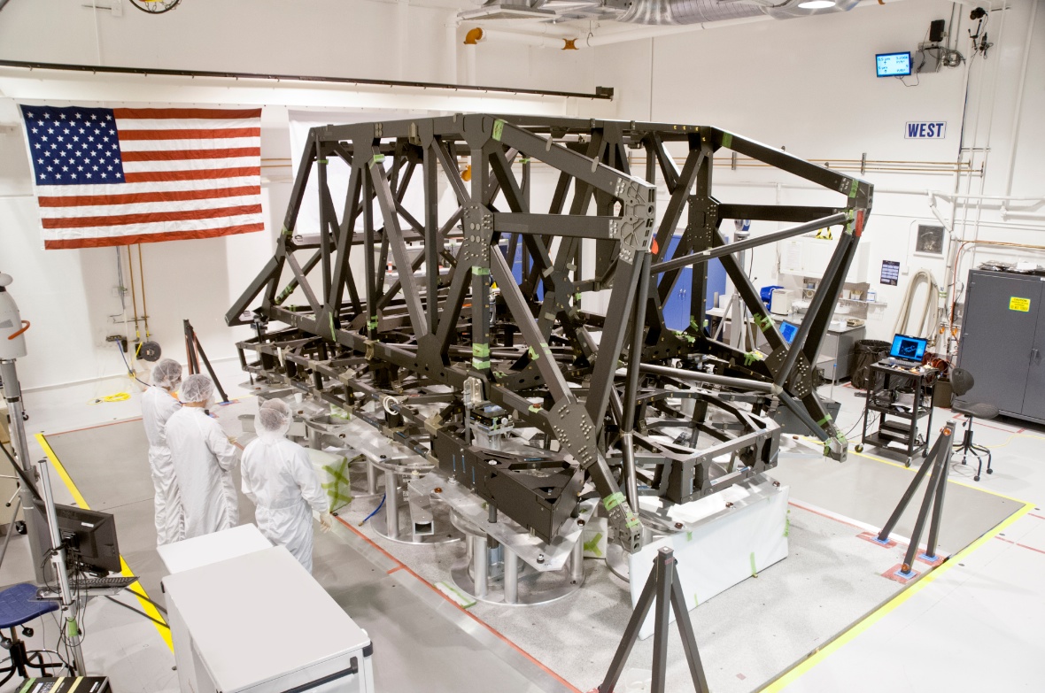
Northrop Grumman and teammate ATK have completed manufacturing of the backplane support frame (BSF) for NASA’s James Webb Space Telescope. Northrop Grumman is under contract to NASA’s Goddard Space Flight Center in Greenbelt, Md., for the design and development of the Webb Telescope’s optics, sunshield and spacecraft.

When combined with the centre section and wings, the support frame will form the primary mirror backplane support structure, the stable platform that holds the telescope’s beryllium mirrors, instruments and other elements. It holds the 18-segment, 21-foot-diameter primary mirror nearly motionless while the telescope is peering into deep space. The backplane support frame is the backbone of the observatory, is the primary load carrying structure for launch, and holds the science instruments.

Living in Sustainable Cities of the Future

Masdar City, United Arab Emirates – This gleaming example of sustainable urban living just 17km east of Abu Dhabi is currently more university and business campus than metropolis, but when Masdar City is complete in 2025, it will be home to 40,000 residents and 50,000 commuters. The city’s master plan, designed by the architects Foster + Partners, put roads underground (and bans cars that use petrol), allowing for very narrow pedestrian streets that capture and funnel the breezes, aided and shaded by thick city walls, a technique Arab builders have used for centuries. The city’s modern elements come in the renewable energy and clean tech sources being developed at the Masdar Institute of Science and Technology, which currently houses 250 students on campus. The city is completely powered by renewable energy sources such as solar, and the buildings are being constructed with recycled materials, including steel and aluminium. Energy and potable water demands have been reduced by more than 50%, using a quarter of the energy of a conventional city the same size. “We are addressing social, economic and environmental sustainability and also making sure it’s affordable,” said Omar Zaafrani, communications manager for Masdar City. The building that houses both the Masdar and International Renewable Energy Agency headquarters will have stores and restaurants in addition to office space, powered by 1,000sqm of photovoltaic panels. While no residential buildings beyond dormitories have been built, they are in the works. “There are various residential plots around the city, and over the coming years they will be tendered out to global architects,” Zaafrani explained. The city’s economic free zone – with zero taxes, import tariffs or restrictions on foreign hires – is set up to specifically attract clean energy and tech companies, clustering them together in incubator office buildings. “The number one target is people who work in Abu Dhabi and around the UAE,” Zaafrani said. “We are trying to make sure as we build up the city, there will be demand for both commercial and residential spaces.” Currently, a four-bedroom villa in central Abu Dhabi rents for around 200,000 dirhams a year, while a two-bedroom flat in Reem Island rents for around 100,000 dirhams. Over the next two years, 45,000 new flats and houses will come available.

New York to Spend Billions on Climate Resiliency

Nearly eight months after Hurricane Sandy slammed the north-eastern United States, New York Mayor Michael Bloomberg is proposing a far-reaching $20 billion plan to build flood barriers and “green infrastructure” to protect low-lying areas of Manhattan from future superstorms.

Following Sandy, the mayor appointed a task force to assess the city’s vulnerability. In a report released this week based on its recommendations, the mayor cited scientists’ predictions that sea levels could rise as much as 31 inches by 2050, accompanied by severe storms and prolonged spells of extreme heat and cold.

“Hurricane Sandy made it all too clear that, no matter how far we’ve come, we still face real, immediate threats,” Bloomberg said in a speech at the Brooklyn Navy Yard, the same location where IceStone, a Sustainable Industries-profiled company, was nearly wiped out following Sandy (in this case, workers rallied to restore the factory). “Much of the work will extend far beyond the next 200 days — but we refuse to pass the responsibility for creating a plan onto the next administration. This is urgent work, and it must begin now.”

Bloomberg’s recommendations are highlighted by “green infrastructure” projects, including supporting renewable and distributed energy generation systems, planting more trees and vegetation on streets and rooftops, upgrading building codes, enhancing natural wetlands, and refurbishing drainage systems to manage runoff. The mayor also  appointed a “director of resilience” named Daniel Zarilli.

The plan is heavy on construction of stormwalls and barriers, but Bloomberg suggested these could come in the form of elevated parks and boardwalks.

The mayor’s report was endorsed by a cadre of business and environmental organizations, including the Columbia University Center on Global Energy Policy, Real Estate Board of New York, Environmental Defense Fund, Building Resiliency Task Force, The Rockefeller Foundation, NRDC, New York Smart Grid Consortium, the American Institute of Architects New York chapter, and the region’s largest energy utility, Con Edision.

“These new guidelines place New York City at the forefront of thinking on resiliency relevant for coastal communities around the world,” said Christopher Collins, executive director of Solar One. “This continues a series of strategic steps that the Bloomberg administration has taken, including investment in new, sustainable building models, to help create a new paradigm for construction that addresses both the fact of climate change, as well as the need for renewable and sustainable practices.”

How will New York pay for it all? The city can rely on $10 billion in city capital funding and federal aid, and another $5 billion in U.S. disaster relief, the mayor said. Additional federal funding and capital raised through the sale of municipal bonds would be needed to cover the remaining $4.5 billion, he added. The plan outlines a number of ways to raise the additional billions that would be required for the plan to become a reality.

Story credit: www.sustainableindustries.com


Loading...